How To Draw A Finite State Machine
Digital Circuits - Finite State Machines
Nosotros know that synchronous sequential circuits alter (touch on) their states for every positive (or negative) transition of the clock signal based on the input. And so, this behavior of synchronous sequential circuits tin can be represented in the graphical form and it is known every bit state diagram.
A synchronous sequential circuit is besides chosen as Finite State Motorcar (FSM), if it has finite number of states. There are ii types of FSMs.
- Mealy State Automobile
- Moore State Machine
Now, allow us talk over almost these two state machines ane by i.
Mealy Country Machine
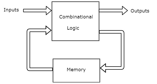
A Finite State Machine is said to exist Mealy land machine, if outputs depend on both present inputs & present states. The block diagram of Mealy land machine is shown in the post-obit effigy.

As shown in figure, there are two parts present in Mealy state auto. Those are combinational logic and retentiveness. Memory is useful to provide some or part of previous outputs (nowadays states) as inputs of combinational logic.
And then, based on the present inputs and present states, the Mealy country machine produces outputs. Therefore, the outputs will be valid but at positive (or negative) transition of the clock signal.
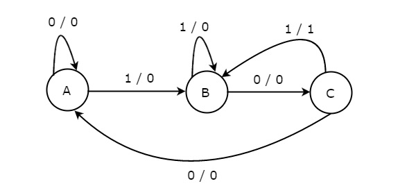
The country diagram of Mealy land machine is shown in the following figure.

In the to a higher place figure, there are three states, namely A, B & C. These states are labelled inside the circles & each circle corresponds to one state. Transitions between these states are represented with directed lines. Here, 0 / 0, 1 / 0 & i / ane denotes input / output. In the above figure, at that place are ii transitions from each country based on the value of input, x.
In general, the number of states required in Mealy state machine is less than or equal to the number of states required in Moore state machine. There is an equivalent Moore country automobile for each Mealy country car.
Moore State Automobile
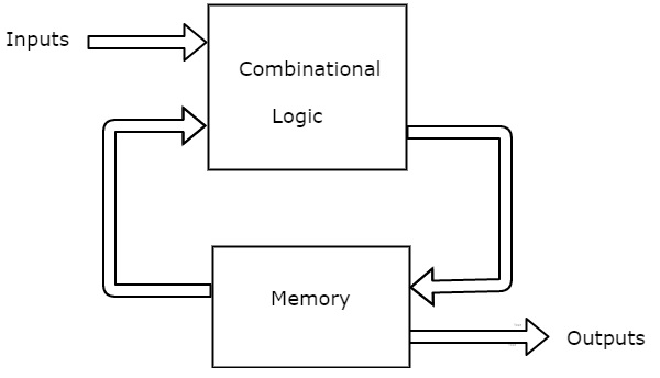
A Finite State Car is said to be Moore state machine, if outputs depend but on present states. The block diagram of Moore state machine is shown in the post-obit figure.

As shown in figure, there are two parts present in Moore state machine. Those are combinational logic and memory. In this example, the present inputs and present states determine the next states. So, based on next states, Moore state machine produces the outputs. Therefore, the outputs will be valid merely after transition of the state.
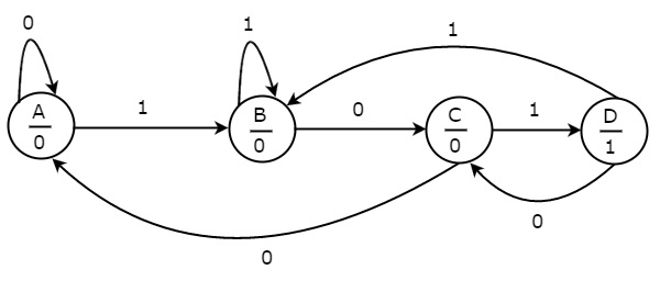
The state diagram of Moore state machine is shown in the post-obit figure.

In the higher up effigy, there are four states, namely A, B, C & D. These states and the corresponding outputs are labelled inside the circles. Here, merely the input value is labeled on each transition. In the above figure, there are two transitions from each state based on the value of input, x.
In general, the number of states required in Moore country machine is more than or equal to the number of states required in Mealy country machine. At that place is an equivalent Mealy state machine for each Moore land motorcar. Then, based on the requirement we can use i of them.
Useful Video Courses

Video

Video

Video

Video

Video

Video
Source: https://www.tutorialspoint.com/digital_circuits/digital_circuits_finite_state_machines.htm
Posted by: sainanderser.blogspot.com


0 Response to "How To Draw A Finite State Machine"
Post a Comment